+8613662928075
 sales@hinicable.com



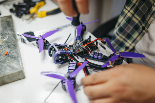
A reliable UAV cable assembly must balance low weight, secure connections, and stable electrical performance. Unmanned aerial vehicles operate under strict payload limits and continuous mechanical vibration. Therefore, every wire, connector, and protective component affects system performance.
Excessive wiring weight reduces the payload available for cameras, sensors, batteries, and other equipment. Poor connector retention can also interrupt power or signal transmission during flight. In critical systems, an unexpected electrical disconnection may cause loss of control or flight failure.
For UAV manufacturers and drone system integrators, cable design requires more than selecting wires with suitable electrical ratings. Engineers must evaluate conductor size, insulation thickness, connector retention, strain relief, routing, and environmental conditions together.
This guide explains the main design considerations for lightweight UAV wiring and reliable custom drone cable assemblies.
1. Weight and Reliability Challenges in Unmanned Aerial Vehicle Wiring
UAV wiring systems face two closely connected challenges: minimizing weight and maintaining electrical reliability. Engineers must reduce unnecessary material without compromising current capacity, insulation performance, or mechanical durability.
1.1 Why Cable Weight Matters in UAV Applications
Unlike many industrial machines, UAVs have limited energy and payload capacity. Their wiring harnesses compete for available weight with batteries, flight controllers, motors, cameras, communication modules, and payload equipment.
Even small weight reductions can become meaningful across multiple cable branches and assemblies.
The main contributors to cable assembly weight include:
- Conductors: Copper cross-sectional area and total cable length.
- Insulation: Material type, wall thickness, and construction.
- Connectors: Housing material, contact size, and locking structure.
- Protective components: Sleeves, tapes, conduits, and braided shielding.
- Mounting hardware: Clips, brackets, cable ties, and support structures.
However, reducing wire diameter without electrical calculations can create excessive voltage drop and conductor heating. Lightweight design should therefore focus on removing unnecessary material rather than simply choosing the thinnest available wire.
1.2 Vibration and Mechanical Stress During Flight
UAV cable assemblies experience continuous mechanical stress from motors, propellers, landing impacts, and airframe movement.
Brushless motors and propellers generate vibration across different operating speeds. These vibrations can transfer through the frame into connectors, solder joints, and cable attachment points.
Common wiring failures include:
- Connector contacts becoming intermittent.
- Terminals loosening under repeated vibration.
- Conductors breaking near rigid termination points.
- Insulation wearing against sharp frame edges.
- Solder joints developing fatigue cracks.
- Cable branches pulling against circuit boards.
These failures may interrupt power or sensor signals. Their consequences depend on the affected circuit and the aircraft’s system architecture.
For example, an unstable power connection to an electronic speed controller (ESC) can interrupt motor operation. An intermittent sensor connection may also affect navigation or flight-control functions.
1.3 Balancing Weight Reduction and Electrical Safety
A lightweight UAV cable assembly should satisfy several requirements simultaneously.
| Design factor | Main consideration | Potential risk if overlooked |
|---|---|---|
| Conductor size | Current, length, voltage drop, and temperature | Overheating or unstable power |
| Insulation | Voltage rating, temperature, and abrasion | Electrical leakage or short circuits |
| Connector | Contact rating and retention | Intermittent connections |
| Cable routing | Bend radius and movement clearance | Wear and conductor fatigue |
| Strain relief | Load transfer at termination points | Broken wires or damaged joints |
| Shielding | Signal sensitivity and electromagnetic environment | Electrical interference |
The correct design depends on the UAV platform, electrical architecture, installation space, and operating conditions.
2. Ultra-Lightweight Components: Thin-Wall Insulations and Micro Connectors
Lightweight construction begins with component selection. Engineers can evaluate conductor materials, insulation systems, and connector dimensions to reduce unnecessary mass.
However, each component must still meet its electrical, thermal, and mechanical requirements.
2.1 Thin-Wall Insulation for Lightweight UAV Wiring
Thin-wall insulation can reduce cable diameter and weight while improving routing flexibility. It may also help engineers fit more wiring into compact UAV frames.
Several insulation materials are worth evaluating.
Polyimide insulation
Polyimide offers high-temperature capability and useful dielectric properties. It is commonly used in specialized electrical applications where thermal performance and compact construction matter.
For UAV applications, engineers should verify its mechanical protection, flexibility, termination compatibility, and suitability for the intended cable construction. Thin insulation alone does not guarantee abrasion resistance.
Fluoropolymer insulation
Materials such as PTFE and ETFE are used in applications requiring specific combinations of temperature resistance, chemical resistance, and electrical performance.
ETFE can be considered for lightweight wire constructions where mechanical durability and flexibility are important. PTFE offers strong thermal and chemical resistance, although its mechanical characteristics and processing requirements need careful evaluation.
Silicone insulation
Silicone-insulated wires provide flexibility across a broad temperature range. They are often considered for battery and motor-related connections where repeated movement or tight routing is expected.
However, silicone insulation can require additional abrasion protection in exposed or high-wear locations.
The best insulation material depends on the actual temperature range, voltage, bending requirements, installation environment, and applicable safety standards.
2.2 Selecting Micro Connectors for Compact Drone Systems
Micro connectors help reduce installation space and simplify wiring in compact UAV electronics.
They may be used in flight controllers, GPS modules, cameras, telemetry systems, sensors, and other low-current electronic circuits.
Common connector families include:
- JST connector series: Selected compact series are widely used in small electronic assemblies and signal connections.
- Molex connector series: Different product families provide compact wire-to-board and wire-to-wire connection options.
- Custom miniature connectors: These may be considered when standard products cannot meet specific space, contact, or retention requirements.
It is important to distinguish connector brands from individual connector series. Not every JST or Molex connector supports the same current, voltage, wire gauge, or vibration conditions.
Before selecting a micro connector, engineers should check:
- Rated current and voltage for each contact.
- Compatible wire gauge and insulation diameter.
- Contact resistance and terminal plating.
- Mating-cycle requirements.
- Locking structure and retention force.
- Operating temperature and environmental conditions.
- Assembly and inspection requirements.
A small connector should never be selected based on size alone. Its electrical rating and mechanical retention must match the application.
2.3 How to Reduce Wiring Weight Without Compromising Performance
A practical lightweight design process should evaluate the complete wiring route rather than individual components in isolation.
Consider these design strategies:
- Shorten unnecessary cable branches.
- Use appropriate conductor sizes based on electrical calculations.
- Select compact connectors for suitable signal circuits.
- Avoid excessive protective sleeves where they are not needed.
- Combine wiring routes when electrical separation and serviceability allow.
- Use lightweight mounting methods with adequate retention.
- Separate high-current and sensitive signal wiring when required.
Engineers should also consider assembly complexity. A design that saves a small amount of cable weight may increase manufacturing errors or maintenance difficulty.
The objective is to achieve a reliable balance between weight, performance, and production consistency.
3. Vibration-Proof Locking Mechanisms and Strain Relief Design
Connector retention is critical for UAV wiring because flight vibration can create repeated mechanical loads. A secure connection must resist unintended separation while allowing practical assembly and maintenance.
3.1 Self-Locking Connectors for Secure Connections
Self-locking connectors use mechanical features to help prevent accidental disconnection.
Depending on the connector family, these features may include:
- Positive locking tabs.
- Friction-locking structures.
- Latching housings.
- Screw-locking mechanisms.
- Secondary locking devices.
For vibration-exposed UAV applications, positive mechanical retention is generally preferable to relying only on contact friction.
However, the locking mechanism must match the connector’s intended operating environment. Small connectors can still experience terminal back-out, housing damage, or wire pullout if assembled incorrectly.
Engineers should verify the connector manufacturer’s retention specifications and assembly instructions.
3.2 Adhesive Reinforcement: When Is Potting or Glue Appropriate?
Adhesive reinforcement can help stabilize selected connector areas or cable transitions. It may reduce movement at vulnerable interfaces when the process and materials are properly controlled.
Possible approaches include:
- Applying compatible adhesive around selected connector housing areas.
- Using potting compounds for designated electronic assemblies.
- Securing cable transitions with approved bonding materials.
- Adding protective compounds to selected exposed termination areas.
However, adhesive should not replace a properly designed locking connector or mechanical strain relief.
Incorrect application can create additional problems:
- Adhesive may enter the contact area.
- Excessive rigidity may transfer stress to the conductor.
- Some chemicals may damage insulation or connector plastics.
- Cured adhesive may complicate inspection and repair.
- Poor surface preparation may cause bonding failure.
For production assemblies, adhesive selection should consider material compatibility, curing conditions, temperature exposure, and maintenance requirements.
3.3 Strain Relief Design for Cable Terminations
Strain relief reduces the mechanical load transferred to electrical termination points.
Without suitable strain relief, repeated cable movement can concentrate stress near solder joints, crimp terminals, or connector exits. This may eventually cause conductor fatigue or insulation damage.
Common strain relief solutions include:
Flexible strain relief tubing
Soft elastomeric tubing can protect cable transitions and reduce localized bending. Its flexibility and dimensions should match the cable diameter and expected movement.
Heat-shrink tubing
Heat-shrink tubing can provide insulation support and environmental protection. Adhesive-lined versions may improve sealing in suitable applications.
However, excessive shrinking or unsuitable tubing stiffness can create a rigid transition.
Molded strain relief
Custom molded strain relief can provide a controlled transition between the cable and connector housing. It may be useful for repeated production applications with consistent geometry.
Cable clamps and routing supports
Properly positioned clamps can reduce vibration transfer and prevent cables from pulling directly on connectors.
The goal is not to eliminate all cable movement. It is to control bending and prevent concentrated mechanical stress.
3.4 Cable Routing and Vibration Testing
Cable routing plays a major role in long-term reliability.
A well-designed UAV wiring harness should:
- Avoid sharp bends near connector exits.
- Maintain the cable manufacturer’s minimum bend radius.
- Keep wires away from propellers and moving mechanisms.
- Prevent contact with sharp frame edges.
- Avoid excessive tension during installation.
- Secure cables without crushing their insulation.
- Separate sensitive signal wiring from noisy power paths where necessary.
Validation should include appropriate vibration and mechanical testing based on the aircraft’s intended operating environment.
Useful checks include connector retention, continuity monitoring, insulation inspection, and post-test examination of terminations.
A vibration test should reflect the relevant frequency range, acceleration levels, mounting conditions, and test duration. One generic vibration profile cannot represent every UAV platform.
4. High-Current Power Looms for ESC and Brushless Motors
UAV power wiring requires particular attention because battery and motor circuits can carry substantial current.
A lightweight cable must still control voltage drop, temperature rise, and electrical losses.
4.1 Selecting High-Current Wires for ESC Connections
An electronic speed controller regulates power delivered to a brushless motor. Its power input and motor phase connections may experience demanding electrical and thermal conditions.
The required conductor size depends on several factors:
- Continuous and peak current.
- Operating voltage.
- Cable length.
- Allowable voltage drop.
- Ambient temperature.
- Installation and cooling conditions.
- Duty cycle and operating duration.
- Connector and terminal ratings.
Silicone-insulated flexible wire is often considered for UAV power connections because it can support flexible routing and repeated movement.
However, insulation material does not determine current capacity by itself. Conductor cross-sectional area, construction, temperature rating, and installation conditions remain essential.
4.2 Understanding Voltage Drop and Heat Generation
Cable resistance creates voltage drop and heat during current flow.
For a simplified DC circuit:
[ V_{\text{drop}} = I \times R ]
Where:
- (V_{\text{drop}}) is the voltage drop.
- (I) is current.
- (R) is the total circuit resistance.
For a two-conductor DC circuit, the conductor resistance can be estimated as:
[ R = \rho \times \frac{2L}{A} ]
Where:
- (\rho) is the conductor resistivity.
- (L) is the one-way cable length.
- (A) is the conductor cross-sectional area.
This simplified calculation does not include connector, terminal, or contact resistance.
Power dissipated as heat can be estimated using:
[ P = I^2R ]
This relationship explains why even a small increase in resistance can create significant heat at high current.
Engineers should evaluate the complete power path, including wires, connectors, solder joints, crimp terminals, and distribution boards.
4.3 Managing Heat in UAV Power Cable Assemblies
Heat management is important for maintaining stable power delivery and protecting nearby components.
Recommended design considerations include:
Correct conductor sizing
Choose conductor sizes based on current, cable length, temperature rise, and installation conditions. Avoid using a generic current rating without considering the actual operating environment.
Low-resistance connections
Use compatible terminals and approved crimping or soldering processes. Poor termination quality can create localized resistance and overheating.
Appropriate connector selection
Verify that connector contacts support the expected continuous and peak current. Consider contact resistance and temperature limits.
Thermal separation
Keep power wiring away from heat-sensitive components where practical. Avoid routing cables directly against hot motor or ESC surfaces unless the cable construction supports the exposure.
Protection against short circuits
Use suitable insulation, secure routing, and electrical protection devices based on the UAV power architecture.
For high-current applications, engineers should validate temperature rise under representative operating loads rather than relying solely on component datasheets.
4.4 Separating Power Wiring and Sensitive Signal Connections
UAV systems often combine high-current power circuits with sensitive communication, sensor, and control signals.
Fast switching in ESC circuits can generate electromagnetic interference. Poor wiring layout may increase coupling into nearby signal cables.
Good wiring practices include:
- Keep sensitive signal wires away from high-current paths when practical.
- Minimize unnecessary parallel routing between noisy and sensitive circuits.
- Use twisted pairs for suitable differential or noise-sensitive signals.
- Apply shielding where the electrical design requires it.
- Maintain proper grounding and return-current paths.
- Avoid creating unintended ground loops.
Shielding is not automatically necessary for every UAV cable. Engineers should evaluate the signal type, cable length, frequency environment, grounding design, and actual interference risk.
5. How to Specify a Custom UAV Cable Assembly
A clear technical specification helps cable manufacturers select suitable materials, connectors, and production processes.
UAV manufacturers and system integrators should provide the following information when requesting a custom drone wiring harness.
| Specification | Information to provide | Why it matters |
|---|---|---|
| Application | Battery, ESC, motor, camera, sensor, or flight controller | Defines electrical and mechanical requirements |
| Cable length | Overall length and branch dimensions | Supports routing and voltage-drop calculations |
| Conductor | Material and cross-sectional area | Determines resistance and current capacity |
| Insulation | Material and temperature requirements | Supports thermal and mechanical protection |
| Connector | Manufacturer, series, pin count, and gender | Ensures mating compatibility |
| Electrical rating | Voltage, continuous current, and peak current | Supports safe component selection |
| Environment | Temperature, humidity, vibration, and exposure | Defines material and validation needs |
| Assembly drawing | Pinout, wire colors, dimensions, and branch locations | Reduces manufacturing ambiguity |
| Testing | Continuity, insulation, pull, or other required tests | Establishes quality acceptance criteria |
For custom production, buyers should also confirm terminal compatibility, crimp tooling, wire preparation, labeling, inspection methods, and traceability requirements.
A detailed drawing and approved sample can help reduce differences between prototype and mass-production assemblies.
6. Quality Control and Testing for UAV Cable Assemblies
A reliable UAV cable assembly requires consistent manufacturing and inspection. Component selection alone cannot guarantee finished-product performance.
6.1 Electrical Testing
Depending on the application, inspection may include:
- Continuity testing: Confirms the intended electrical paths.
- Pinout verification: Checks that connector terminals match the wiring diagram.
- Short-circuit testing: Identifies unintended connections between circuits.
- Insulation resistance testing: Evaluates insulation performance under specified test conditions.
- Contact resistance testing: Checks resistance across selected electrical interfaces.
Test voltage and acceptance limits must follow the applicable component specifications and customer requirements. Testing should not expose sensitive electronics to unsuitable test conditions.
6.2 Mechanical Inspection
Mechanical quality checks may include:
- Terminal crimp inspection.
- Wire pull testing where specified.
- Connector locking verification.
- Strain relief inspection.
- Cable length and branch dimension checks.
- Visual inspection for insulation damage.
- Verification of labels and connector orientation.
Crimp quality is particularly important. Incorrect crimp height, tooling, or wire compatibility can create high-resistance connections or weak mechanical retention.
6.3 Environmental and Application-Based Validation
For demanding UAV applications, buyers may require additional validation.
Examples include:
- Vibration testing.
- Thermal cycling.
- Temperature-rise testing under load.
- Flex and bending evaluation.
- Connector mating-cycle testing.
- Environmental exposure testing.
Not every assembly needs every test. The test plan should reflect the aircraft’s operating conditions, system criticality, applicable standards, and customer acceptance requirements.
7. Frequently Asked Questions About UAV Cable Assemblies
Q1: What is a UAV cable assembly?
A UAV cable assembly is a group of wires, connectors, terminals, and protective components designed to connect electrical systems inside an unmanned aerial vehicle.
It may support battery power, ESC connections, motors, flight controllers, sensors, cameras, and communication equipment.
Q2: How can a drone wiring harness reduce overall weight?
Engineers can optimize cable lengths, conductor sizes, insulation materials, connector dimensions, and protective components.
However, every reduction must maintain sufficient electrical capacity, insulation performance, and mechanical reliability.
Q3: Which wire insulation is suitable for UAV cable assemblies?
The selection depends on temperature, flexibility, abrasion, chemical exposure, and electrical requirements.
Silicone, ETFE, PTFE, and polyimide-based constructions may be considered for different applications. Engineers should evaluate the complete wire construction rather than insulation material alone.
Q4: Are JST and Molex connectors suitable for drone applications?
Selected JST and Molex connector series can be suitable for compact UAV electronic systems.
However, suitability depends on the specific series, contact rating, wire compatibility, locking structure, and vibration environment.
Q5: How can UAV connectors prevent accidental disconnection?
Use connectors with appropriate mechanical locking features and verify their retention performance.
Correct terminal crimping, cable routing, and strain relief also help reduce mechanical loads on the connection.
Adhesive reinforcement may support selected designs, but it should not replace proper connector retention.
Q6: Why are silicone wires commonly considered for UAV power connections?
Silicone-insulated wires offer flexibility and useful temperature characteristics.
They can support compact routing and movement in suitable applications. However, conductor sizing and actual thermal performance must still be evaluated.
Q7: What tests should a custom UAV cable assembly undergo?
Typical tests may include continuity, pinout, short-circuit, insulation resistance, and visual inspection.
Additional vibration, pull, flex, and temperature-rise testing may be required depending on the application.
Conclusion: Designing Lightweight and Reliable UAV Cable Assemblies
A high-quality UAV cable assembly must balance weight, electrical performance, and mechanical durability.
Lightweight conductors and compact connectors help reduce unnecessary mass. However, wire sizing must still account for current, voltage drop, and temperature rise.
Secure locking mechanisms, suitable strain relief, and controlled cable routing help protect connections against flight vibration. Meanwhile, appropriate power wiring and signal separation support stable electrical operation.
The most reliable design process evaluates the complete wiring system rather than individual components. Material selection, connector compatibility, manufacturing quality, and application-based testing all contribute to long-term performance.
For UAV manufacturers and drone system integrators, working with an experienced custom cable assembly supplier can help translate electrical drawings and installation requirements into production-ready wiring solutions. HINI-Cable welcomes inquiries for custom UAV cable assembly projects, including wire specifications, connector requirements, cable lengths, and assembly drawings.