+8613662928075
 sales@hinicable.com



A reliable servo motor cable assembly must transmit power and feedback signals without compromising system performance. Servo motors depend on stable electrical connections, accurate encoder feedback, and effective electromagnetic interference (EMI) control. However, selecting the wrong cable structure or connector can cause signal errors, intermittent connections, and unexpected equipment downtime.
Industrial automation systems also place different demands on cable assemblies. Some cables remain stationary inside control cabinets. Others move continuously with robotic arms, CNC machines, or linear motion axes.
Therefore, engineers should evaluate electrical performance, shielding, connector compatibility, mechanical protection, and cable flexibility together. This guide explains how to select servo motor power and feedback cables for different industrial applications.
1. The Dual-System Architecture of Servo Cable Assemblies
A servo system typically uses two essential electrical pathways: power transmission and feedback communication. Each pathway performs a different function and requires suitable cable construction.
Understanding these differences is the first step in designing a reliable servo motor cable assembly.
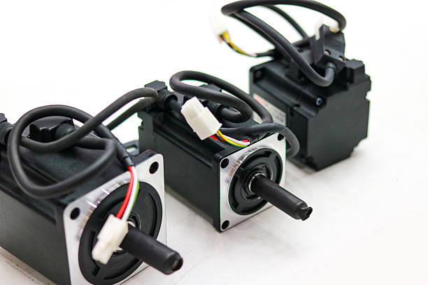
1.1 Servo Power Cables: Delivering Electrical Energy
Servo power cables connect the servo drive to the motor. They carry electrical energy required for motor operation.
Depending on the servo system, these cables may carry three-phase motor power, protective earth, and additional conductors for braking or temperature monitoring.
Common design considerations include:
- Conductor size: The conductor cross-section must support the motor’s rated current and installation conditions.
- Voltage rating: Cable insulation must match the system’s operating voltage and applicable requirements.
- Insulation material: PVC, PUR, and other industrial insulation materials offer different mechanical and environmental properties.
- Temperature resistance: Cable materials must withstand expected operating temperatures.
- Shielding: Appropriate shielding helps control electromagnetic emissions and coupling into nearby circuits.
- Grounding: Protective earth and shield termination must follow the drive and motor manufacturer’s requirements.
A servo power cable should not be selected by conductor size alone. Engineers must also consider cable length, voltage drop, installation temperature, current rating, and the drive manufacturer’s specifications.
Some servo systems also use separate motor brake cables. Others integrate brake conductors into a combined cable structure. The correct configuration depends on the motor and drive interface.
1.2 Servo Encoder Cables: Transmitting Accurate Feedback
Servo encoder cables transmit position, speed, and other feedback information from the motor to the drive.
The encoder interface may use incremental signals, absolute communication protocols, or manufacturer-specific feedback systems.
Unlike power conductors, encoder signal circuits can be sensitive to electrical noise and signal distortion.
Important design factors include:
- Signal compatibility: Match the cable structure to the encoder interface and transmission method.
- Pair arrangement: Differential signal circuits commonly require appropriately twisted pairs.
- Impedance: Some high-speed feedback interfaces require controlled characteristic impedance.
- Shielding: Shielding helps reduce interference from external electrical sources.
- Conductor consistency: Stable electrical characteristics support reliable signal transmission.
- Connector pinout: Correct pin assignment is essential for communication and feedback accuracy.
A servo encoder cable must match the actual encoder specification. A cable suitable for one feedback protocol may not support another.
1.3 Power Cable vs. Encoder Cable: Key Differences
Power and feedback cables serve different electrical purposes. Their design requirements should therefore remain distinct.
| Selection Factor | Servo Power Cable | Servo Encoder Cable |
|---|---|---|
| Main function | Motor power transmission | Position and speed feedback |
| Electrical characteristics | Higher current and voltage requirements | Low-level or high-speed signals |
| Conductor design | Selected for current capacity | Selected for signal requirements |
| Twisted pairs | Not always required | Commonly used for differential signals |
| Shielding | Helps control emissions and interference | Helps protect sensitive feedback signals |
| Main risks | Overheating, voltage drop, insulation failure | Signal errors, noise, communication loss |
| Selection priority | Current, voltage, temperature, installation | Protocol, impedance, shielding, pinout |
Some manufacturers offer combined power and feedback cable assemblies. These products integrate multiple circuits into one cable structure.
However, combined designs require careful electrical separation, shielding, and compatibility checks. Separate cables may provide more installation flexibility in some applications.
1.4 When Should Buyers Choose Separate or Combined Cable Assemblies?
Separate power and encoder cables allow engineers to control routing and cable replacement independently.
They can also simplify maintenance when power and feedback interfaces have different connector requirements.
Combined cable assemblies may reduce cable volume and simplify installation. They can also support compact machine layouts.
Before choosing either design, buyers should confirm:
- Whether the servo drive supports a combined cable arrangement.
- Whether power and feedback circuits require separate shielding.
- Whether the cable must withstand continuous movement.
- Whether the connector system supports the required pin configuration.
- Whether the manufacturer’s wiring instructions permit the proposed layout.
The best solution depends on the servo system architecture rather than cable appearance or conductor count alone.
2. Preventing Electromagnetic Interference (EMI) in Servo Systems
Electromagnetic interference is a major consideration in servo cable design.
Servo drives use switching power electronics to control motor speed and torque. These switching operations can generate electrical noise and fast voltage transitions.
When power and feedback cables run close together, electromagnetic coupling may affect sensitive encoder signals.
A properly designed servo motor cable assembly helps reduce this risk through cable construction, shielding, grounding, and installation practices.
2.1 Why Servo Power Cables Can Interfere with Encoder Signals
Servo motor power cables may carry high-frequency switching components in addition to the motor’s fundamental electrical frequency.
These components can create conducted and radiated electromagnetic disturbances.
When a power cable runs parallel to an encoder cable over a long distance, capacitive and inductive coupling may transfer unwanted noise into the feedback circuit.
Possible symptoms include:
- Encoder communication errors.
- Position feedback instability.
- Unexpected servo alarms.
- Intermittent motor operation.
- Reduced control accuracy.
- Unexplained system interruptions.
However, not every encoder fault results from EMI. Incorrect wiring, poor grounding, damaged connectors, incompatible cable characteristics, and faulty equipment can produce similar symptoms.
Engineers should evaluate the complete electrical installation before replacing cables.
2.2 Aluminum Foil and Copper Braiding: Understanding Double Shielding
Double shielding is one possible construction for industrial servo cables.
A common design combines aluminum foil with a tinned copper braided shield. Each layer provides different shielding characteristics.
Aluminum foil shielding
- Provides broad coverage around the cable core.
- Helps reduce high-frequency electromagnetic coupling.
- Offers relatively lightweight shielding construction.
- May require additional mechanical protection because thin foil can be vulnerable to repeated flexing.
Tinned copper braided shielding
- Provides a conductive shielding layer.
- Offers mechanical flexibility in suitable constructions.
- Supports low-impedance shield connections when properly terminated.
- Helps provide coverage against electromagnetic interference across a broad frequency range.
Combining these layers can improve shielding coverage and performance. However, the result depends on foil coverage, braid coverage, braid density, cable geometry, and termination quality.
Double shielding is not automatically necessary for every servo application. The required construction should follow the drive manufacturer’s recommendations and the system’s EMC requirements.
2.3 Shield Termination and Grounding Matter
Even a well-shielded cable may perform poorly if its shield connection is incorrect.
The shield should be terminated according to the equipment manufacturer’s EMC design instructions.
In many industrial drive installations, a circumferential or 360-degree shield connection at the connector or cable gland provides a lower-impedance path than a long drain-wire connection.
However, the correct grounding arrangement depends on the drive, motor, connector, and machine bonding design.
Engineers should verify:
- Whether the cable shield connects to the motor housing and drive chassis.
- Whether the connector provides a conductive shield termination.
- Whether the cable gland maintains shield continuity.
- Whether the machine has an effective protective bonding arrangement.
- Whether the installation follows the manufacturer’s EMC instructions.
Protective earth and cable shielding serve related but different purposes. They should not be treated as interchangeable.
2.4 Separate Power and Signal Cable Routing
Cable routing is another important part of EMI control.
Even when engineers select shielded cables, poor installation practices may increase interference risks.
Recommended practices include:
- Route servo power cables and encoder cables through separate cable paths where practical.
- Avoid long parallel runs between high-current power cables and sensitive feedback cables.
- Maintain suitable separation based on the equipment manufacturer’s EMC guidance.
- Use separate cable compartments or dividers when the machine design allows.
- Cross power and signal cables at approximately right angles when crossing cannot be avoided.
- Keep cable lengths and routing consistent with the drive manufacturer’s recommendations.
- Avoid unnecessary cable loops and excessive bundled cable lengths.
The required separation distance is not universal. It depends on cable construction, shielding, current, switching characteristics, installation geometry, and EMC requirements.
For compact machines, engineers may need to use additional shielding, suitable cable carriers, or separate routing channels.
2.5 EMI Prevention Checklist for Servo Cable Assemblies
| Design Area | Recommended Consideration | Buyer Verification |
|---|---|---|
| Power cable | Suitable insulation and conductor size | Current and voltage ratings |
| Encoder cable | Compatible signal construction | Encoder protocol and pinout |
| Shielding | Foil, braid, or combined shielding | Coverage and shielding construction |
| Grounding | Proper shield termination | Drive and motor instructions |
| Routing | Separate power and feedback paths | Machine installation layout |
| Connectors | Reliable shield continuity | Connector grounding design |
| Testing | Verify electrical and EMC performance | Relevant test documentation |
A reliable EMI solution requires coordination between cable design and machine installation. Shielding alone cannot compensate for incorrect wiring or grounding.
3. Industrial Servo Connector Options: M12, M23, and Heavy-Duty Connectors
Connectors are critical interfaces in a servo motor cable assembly.
They must maintain electrical continuity under operating loads while resisting vibration, contamination, and mechanical stress.
Connector selection should consider pin count, current rating, voltage rating, signal type, mounting space, locking method, and environmental protection.
3.1 M12 Circular Connectors
M12 connectors are compact circular connectors commonly used in industrial automation.
They are suitable for many sensor, control, and signal connections. Some specialized versions also support power applications.
Typical advantages include:
- Compact dimensions for space-constrained installations.
- Standardized mechanical interfaces within compatible connector families.
- Screw-locking or other specified locking mechanisms.
- Options for different pin counts and coding systems.
- Availability in straight and angled configurations.
However, M12 connectors are not universally suitable for every servo motor power connection.
Their electrical ratings, coding, pin arrangement, and intended application must match the equipment interface.
For example, an M12 connector designed for sensor signals should not be assumed to support a high-current motor power circuit.
3.2 M23 Servo Connectors
M23 circular connectors are widely used in industrial motor and automation interfaces.
They provide more space for contacts than many compact connector formats. This can support applications requiring multiple power, feedback, or auxiliary connections.
Depending on the product design, M23 connectors may offer:
- Power contact configurations.
- Signal and encoder contact configurations.
- Combined power and signal arrangements.
- Shielded housing options.
- Screw-locking or quick-locking mechanisms.
- Different contact layouts and cable exit configurations.
M23 is not a single universal pinout. Different manufacturers and product series may use different contact arrangements.
Before ordering a custom M23 servo cable assembly, buyers should provide the exact connector manufacturer, series, model, and wiring diagram.
3.3 Heavy-Duty Industrial Connectors
Heavy-duty rectangular connectors are used in industrial environments where multiple electrical circuits require a protected connection.
They are common in machine tools, industrial equipment, control cabinets, and modular machinery.
Potential advantages include:
- Multiple contacts within one housing.
- Configurable inserts for different circuit requirements.
- Protective metal or polymer housings.
- Locking mechanisms designed for industrial use.
- Options for environmental sealing.
Heavy-duty connectors can simplify complex machine wiring. However, buyers must verify the insert arrangement, contact ratings, conductor compatibility, and housing protection.
They should also consider maintenance access and the possibility of incorrect mating between similar connector configurations.
3.4 IP67 and Quick-Locking Connector Structures
IP67-rated connectors are designed to provide protection against dust ingress and temporary immersion under specified test conditions when correctly mated and installed.
This rating can be useful in industrial environments exposed to dust, moisture, or occasional water contact.
However, IP67 does not automatically mean a connector is suitable for continuous underwater operation, high-pressure washing, or every chemical environment.
The complete connection system matters. Buyers should evaluate:
- Connector sealing structure.
- Mating condition.
- Cable gland sealing.
- Panel mounting interface.
- Seal material compatibility.
- Temperature and chemical exposure.
- Connector wear and maintenance requirements.
Quick-locking structures can reduce connection time and improve installation convenience.
However, quick-locking does not automatically guarantee vibration resistance. The locking mechanism must be suitable for the actual vibration environment.
For high-vibration applications, engineers should check the connector manufacturer’s retention specifications and verify connection stability under representative operating conditions.
3.5 Connector Selection Comparison
| Connector Type | Common Application | Main Advantages | Important Checks |
|---|---|---|---|
| M12 | Sensors and compact control or signal connections | Compact size and standardized interfaces | Coding, pin count, current rating |
| M23 | Servo motor power and feedback interfaces | Multiple contact configurations | Pinout, voltage, current, locking |
| Heavy-duty connector | Machine and equipment interfaces | Configurable contacts and protected housing | Insert layout, housing, sealing |
| IP67 connector variant | Dust- and moisture-exposed installations | Defined ingress protection when properly installed | Mating seals and installation conditions |
The connector name alone is not enough to confirm compatibility.
A custom servo cable assembly should match the exact motor and drive interfaces. Buyers should provide connector drawings, part numbers, pin assignments, and installation requirements.
4. Cable Flex Requirements for Moving Servo Axis Configurations
Not every servo cable operates under the same mechanical conditions.
A cable installed inside a stationary control cabinet experiences different stress from one moving continuously with a robotic arm or CNC axis.
Selecting the wrong cable construction may cause conductor fatigue, insulation damage, or shield deterioration.
Therefore, engineers should distinguish between fixed-installation cables and dynamic-motion cables.
4.1 Fixed Installation: Prioritizing Electrical and Environmental Performance
Fixed servo cables remain in a stationary position after installation.
Typical applications include:
- Control cabinet wiring.
- Stationary machine connections.
- Fixed motor installations.
- Cable sections inside protected equipment enclosures.
These applications generally place less repeated bending stress on conductors.
Selection should focus on:
- Rated voltage and current.
- Conductor cross-section.
- Insulation temperature range.
- Shielding and grounding.
- Chemical and environmental resistance.
- Applicable installation standards.
- Required bending radius during installation.
A cable suitable for fixed installation should not automatically be used in a moving cable carrier.
4.2 Dynamic Installation: Selecting Flexible Servo Cables
Dynamic servo cables operate under repeated movement.
They may travel through drag chains, move with linear axes, or follow robotic arm motion.
These applications require more than a flexible outer jacket. The conductor, insulation, shielding, and internal cable geometry must support the expected motion.
Important factors include:
Conductor stranding
Fine-stranded conductors can improve flexibility compared with solid or less flexible conductor constructions.
However, conductor stranding alone does not determine cable service life. Strand design, material quality, and cable construction also matter.
Insulation and jacket materials
PUR jackets are commonly used in demanding industrial cable applications because selected formulations provide abrasion and mechanical resistance.
PVC may be suitable for certain fixed or less demanding applications.
Material selection should consider temperature, oil exposure, chemicals, abrasion, and movement conditions.
Shield flexibility
A shield designed for fixed installation may not withstand repeated bending equally well.
Dynamic servo cables need a shielding construction suitable for their movement profile.
Internal cable geometry
Conductor arrangement, filler materials, lay length, and core construction influence bending behavior.
A well-designed dynamic cable maintains stable internal geometry during repeated movement.
4.3 Drag Chain Applications: What Buyers Should Confirm
Drag chains guide cables along moving machine axes.
However, cable performance depends on the actual cable carrier and operating conditions.
Before selecting a flexible servo motor cable assembly, buyers should confirm:
- Travel distance: The total movement length of the axis.
- Travel speed: The maximum linear movement speed.
- Acceleration: The acceleration and deceleration profile.
- Bending radius: The minimum bending radius specified by the cable manufacturer.
- Cycle frequency: The number of movement cycles expected.
- Cable arrangement: The number of cables inside the carrier and their installation positions.
- Temperature: The operating temperature inside and around the carrier.
- External exposure: Oil, coolant, dust, abrasion, and other environmental factors.
Cable carriers also require suitable installation practices.
Cables should have enough space to move freely without excessive tension or compression. Their arrangement should avoid twisting, crossing, and unnecessary contact with sharp edges.
The carrier manufacturer’s filling and installation recommendations should also be followed.
4.4 Fixed vs. Dynamic Servo Cable Requirements
| Design Factor | Fixed Installation | Dynamic Installation |
|---|---|---|
| Main mechanical stress | Installation and static loading | Repeated bending and movement |
| Conductor construction | Selected for electrical requirements | Fine-stranded construction may be required |
| Jacket requirements | Environmental and installation protection | Flexibility and abrasion resistance |
| Shield construction | Suitable for stationary EMC conditions | Suitable for repeated flexing |
| Bending radius | Installation minimum | Continuous-motion minimum |
| Testing priority | Electrical and environmental tests | Electrical, mechanical, and flex-life tests |
| Typical application | Cabinets and stationary equipment | Drag chains and moving axes |
A dynamic cable should be selected using its specified movement conditions rather than a general description such as flexible or industrial grade.
4.5 Why Continuous Flex Life Should Be Verified
Cable flex life is not determined by one universal cycle count.
Actual performance depends on bending radius, travel speed, acceleration, cable arrangement, temperature, and test conditions.
Two cables with similar materials may deliver different results under the same movement profile.
When sourcing a custom servo cable assembly for moving equipment, buyers should request relevant technical information, such as:
- Specified minimum bending radius.
- Approved cable carrier applications.
- Tested movement conditions.
- Flex-cycle test results, where available.
- Temperature range during dynamic operation.
- Shield continuity or electrical performance after testing.
A documented test result is more useful when it includes the test setup and operating conditions.
5. How to Specify a Custom Servo Motor Cable Assembly
A clear technical specification helps manufacturers evaluate cable structure, connector compatibility, and production requirements.
Before requesting a quotation, buyers should prepare the following information.
5.1 Electrical Specifications
- Servo motor and drive models.
- Rated voltage and current.
- Power conductor quantity and cross-section.
- Encoder or feedback protocol.
- Signal conductor quantity.
- Required impedance, if specified.
- Brake or temperature sensor requirements.
- Cable length.
5.2 Connector Specifications
- Motor-side connector manufacturer and model.
- Drive-side connector manufacturer and model.
- Connector type and coding.
- Pin count and pin assignment.
- Cable exit direction.
- Locking mechanism.
- Required environmental protection.
5.3 Mechanical and Environmental Specifications
- Fixed or dynamic installation.
- Drag chain or robotic movement requirements.
- Minimum bending radius.
- Travel distance and speed.
- Expected flex cycles.
- Operating temperature.
- Oil, coolant, moisture, and chemical exposure.
- Installation and routing constraints.
5.4 Quality and Testing Requirements
Depending on the application, buyers may request:
| Test or Inspection | Purpose |
|---|---|
| Continuity test | Confirms electrical connections |
| Pinout verification | Checks correct conductor assignment |
| Insulation resistance test | Evaluates insulation condition |
| Dielectric withstand test | Verifies insulation withstand capability under specified conditions |
| Shield continuity test | Checks shielding connection |
| Connector inspection | Verifies assembly and mating condition |
| Flex testing | Evaluates performance under specified movement conditions |
| Dimensional inspection | Checks cable and connector dimensions |
Not every test applies to every cable assembly. The inspection plan should match the product design, applicable standards, and customer requirements.
6. Conclusion: Building a Reliable Servo Motor Cable Assembly
A reliable servo motor cable assembly depends on coordinated electrical, mechanical, and connector design.
Power cables must support the motor’s electrical requirements. Encoder cables must preserve feedback signal integrity. Shielding and grounding help reduce EMI risks, while correct cable routing further improves system reliability.
Connector selection also matters. M12, M23, and heavy-duty connectors serve different applications, and buyers must verify their exact electrical ratings, pinouts, locking structures, and environmental protection.
For moving servo axes, cable construction must match the actual bending radius, travel speed, cycle frequency, and installation environment.
In practice, the best cable assembly is not simply the one with the most shielding or the highest flexibility rating. It is the one that matches the servo drive, motor, installation conditions, and operating requirements.
For custom projects, HINI-Cable can work with buyers to evaluate cable specifications, connector configurations, shielding structures, and assembly requirements. Providing motor and drive models, wiring diagrams, and motion conditions helps establish a more accurate cable design.
Frequently Asked Questions
1. What is a servo motor cable assembly?
A servo motor cable assembly is a preconfigured cable system that connects a servo motor with its drive or control equipment. It may include power conductors, encoder feedback circuits, connectors, shielding, and auxiliary wiring.
2. What is the difference between a servo power cable and an encoder cable?
A servo power cable delivers electrical energy to the motor. An encoder cable transmits position, speed, or other feedback signals to the drive. They require different conductor designs and electrical characteristics.
3. Does a servo motor cable need double shielding?
Not every servo cable requires double shielding. Aluminum foil and copper braid can provide complementary shielding characteristics. The correct design depends on the drive manufacturer’s EMC requirements, installation conditions, and signal sensitivity.
4. Can servo power cables and encoder cables run together?
They can be installed within the same machine, but separate routing is generally preferable where practical. Long parallel runs may increase electromagnetic coupling. Follow the drive manufacturer’s separation and EMC installation recommendations.
5. What is the difference between M12 and M23 servo connectors?
M12 connectors are compact and commonly used for sensor and signal connections. M23 connectors offer different contact configurations for industrial motor and feedback interfaces. Actual suitability depends on connector ratings, pinout, and equipment compatibility.
6. Is IP67 necessary for servo cable connectors?
IP67 may be useful in applications exposed to dust or temporary water immersion under specified test conditions. It is not universally required. Buyers should assess the actual environment and verify the complete connector assembly’s protection rating.
7. What type of servo cable is suitable for drag chains?
Drag chain applications generally require cables designed for repeated movement. Buyers should verify conductor construction, jacket material, shield flexibility, minimum bending radius, and tested movement conditions.
8. What information is needed to customize a servo motor cable assembly?
Provide the motor and drive models, cable length, voltage and current requirements, encoder protocol, connector part numbers, pinout, shielding requirements, and installation conditions. For dynamic applications, also provide travel speed, bending radius, and expected cycle frequency.