+8613662928075
 sales@hinicable.com

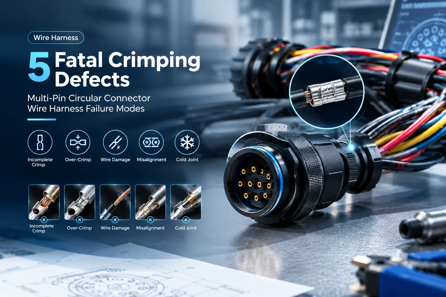
In critical industrial applications—such as robotics, factory automation, aerospace, and medical equipment—the multi-pin circular connector wire harness serves as the vital central nervous system transmitting high-speed data and heavy power. Because circular connectors house dozens of high-density pin contacts within a compact shell, every single pin crimp joint must perform flawlessly.
While mechanical failures like damaged connector shells or outer cable tears are easy to detect during visual inspection, crimping defects act as “invisible killers.” These microscopic flaws pass basic continuity testing at the factory, only to trigger intermittent signal dropouts, localized overheating, or catastrophic system failure once deployed under real-world vibration and thermal stress.
As a specialized industrial custom wire harness manufacturer, HINI-Cable systematically breaks down the 5 most critical crimping defects in circular connector harnesses, analyzing their mechanical root causes, thermal consequences, and quality control solutions.
1. The Mechanics of Crimp Quality in Circular Connector Pins
A proper crimp joint creates a cold-welded, gas-tight connection between the stranded copper conductor and the connector’s metal terminal barrel.
               OPTIMAL PIN CRIMP JOINT ANATOMY

  [ Insulation Crimp Area ] ──► Secures Cable Jacket against Strain
  [ Rear Bellmouth ]         ──► Prevents Sharp Edge Wire Shearing
  [ Wire Conductor Crimp ]   ──► Gas-Tight Cold Weld (Low Resistance)
  [ Front Bellmouth ]        ──► Ensures Smooth Pin Insertion into Shell
When pressure is applied via precision crimping tools, the terminal barrel deforms around the copper strands, eliminating internal air voids without fracturing individual wires. Deviations in strip length, terminal insertion depth, or crimp height compromise both mechanical pull-out strength and electrical conductivity.
2. The 5 Fatal Crimping Defects in Multi-Pin Harness Assembly
Preventing field failures requires identifying subtle defects during process validation before final potting or connector assembly.
2.1: Wire Strands Sticking Out / Stray Strands (Outside Bellmouth)
-
The Defect: Individual copper wire strands flare out outside the conductor crimp zone instead of being fully captured within the terminal barrel.
-
Root Cause: Improper wire stripping, twisted strand unraveling during handling, or incorrect terminal size selection.
-
Consequences: In high-density multi-pin circular connectors (such as M12, M23, or MIL-DTL-38999 standards), a single stray strand can bridge the tiny gap between adjacent contact pins, causing short circuits, signal cross-talk, or catastrophic arc faults.
2.2: Insulation Trapped in Conductor Crimp Area
-
The Defect: The outer wire insulation extends into the primary metal conductor crimp zone.
-
Root Cause: Inaccurate wire strip length (too short) or over-insertion of the wire into the terminal locator during manual crimping.
-
Consequences: Plastic insulation acts as an electrical insulator. Trapping insulation inside the metal-to-metal crimp zone drastically increases contact resistance ($R = \frac{V}{I}$). Under high-current power transmission, this high resistance creates severe localized joule heating, melting the connector insert and posing a fire hazard.
2.3: Cracks in the Terminal Crimp Barrel
-
The Defect: Visible micro-cracks or structural fractures along the seam or sides of the crimped metal terminal barrel.
-
Root Cause: Excessive crimp force, unapproved die tooling, or sub-standard terminal raw materials with low ductility.
-
Consequences: Cracks destroy the structural integrity of the cold weld. Over time, ambient humidity and industrial atmospheric gases penetrate the cracked barrel, accelerating copper oxidation and contact corrosion, which ultimately causes open circuits under vibration.
2.4: Excessive Gap Between Insulation Crimp and Conductor Crimp
-
The Defect: An oversized gap of exposed bare copper wire between the rear insulation support crimp and the main conductor crimp zone.
-
Root Cause: Excessive strip length or improper terminal feed position during automated crimping.
-
Consequences: The bare copper wire loses physical support. Under continuous dynamic bending, robot arm movement, or mechanical vibration, stress concentrates on the unsupported wire section, causing rapid metal fatigue and wire strand breakage.
2.5: Crimp Height Out of Manufacturer Tolerance
-
The Defect: The measured crimp height ($CH$) falls above or below the terminal manufacturer’s strict engineering specification.
-
Root Cause: Worn crimp tooling dies, incorrect applicator adjustment, or incorrect wire gauge (AWG) matching.
-
Consequences:
-
Under-crimping (Height too high): Inadequate compaction leaves internal gas voids, resulting in low mechanical pull-out force and loose electrical contact.
-
Over-crimping (Height too low): Excessive force severe wire strands and thins the terminal wall, weakening joint strength and causing early fatigue failure.
-
3. Defect Analysis & Impact Matrix
Evaluating crimping defects across physical parameters helps quality assurance teams enforce zero-defect manufacturing:
| Crimping Defect Mode | Primary Cause | Electrical Impact | Mechanical Impact | Inspection Method |
| Stray Strands Outside Barrel | Poor wire stripping & manual handling | Short circuit risk between adjacent pins | Decreased tensile pull-out strength | High-magnification optical inspection |
| Insulation in Conductor Zone | Short strip length / over-insertion | Spike in contact resistance; severe overheating | Reduced mechanical crimp lock | Micro-section cross-section analysis |
| Cracked Crimp Barrel | Over-compression / defective terminal metal | Accelerated pin corrosion & signal noise | Complete loss of structural integrity | Inline vision systems & die check |
| Excessive Insulation Gap | Over-stripping / improper wire placement | Exposed conductor short-circuit risk | High stress concentration; strand fatigue | Automated wire strip camera verification |
| Out-of-Spec Crimp Height | Tooling wear / incorrect applicator setup | Loose contact or high resistance | Wire shearing or low pull-out force | Precision Crimp Height Micrometer / Pull Test |
4. How HINI-Cable Ensures Zero-Defect Harness Manufacturing
Eliminating invisible crimping flaws requires combining automated manufacturing controls with rigorous quality validation:
-
100% Crimp Force Monitoring (CFM): Every automated crimping press at HINI-Cable is equipped with real-time crimp force sensors that detect micro-variations in compaction force, instantly rejecting defective crimps.
-
Micro-Section Cross-Section Analysis: We perform destructive micro-sectioning on sample production batches to measure strand deformation ratios, gas-tight integrity, and terminal wall thickness under high-power microscopes.
-
Automated Optical Inspection (AOI): Vision cameras inspect strip lengths, bellmouth dimensions, and strand containment before contacts are snapped into circular connector housings.
-
Pull-Force & Electrical Testing: Every batch undergoes calibrated pull-out force testing and 100% high-voltage hipot and continuity testing to guarantee long-term field reliability.
Summary & Sourcing Custom Industrial Harnesses with HINI-Cable
Building a reliable multi-pin circular connector wire harness requires absolute control over terminal crimp geometry. Avoiding stray strands, insulation entrapment, barrel cracks, excessive gaps, and improper crimp heights prevents high contact resistance, thermal runaway, and unexpected system downtime in demanding industrial environments.
Partner with HINI-Cable for High-Reliability Industrial Harness Solutions
At HINI-Cable, we specialize in designing, prototyping, and manufacturing custom industrial wire harnesses, multi-pin circular connector assemblies, and heavy-duty cable systems for global machinery builders, automation integrators, and medical device manufacturers.
-
Precision Custom Engineering: Customized pin layouts, shielded cable constructions, IP67/IP68 overmolding, and custom connector integration tailored to your exact application.
-
Strict Quality Compliance: Manufactured under ISO 9001 quality systems, complying with IPC/WHMA-A-620 workmanship standards for commercial and industrial wire harnesses.
-
Comprehensive B2B Support: From DFM (Design for Manufacturability) guidance and rapid harness prototyping to full-volume production and 100% electrical testing.
Eliminate hidden harness failures in your industrial equipment. Contact the engineering team at HINI-Cable today to request technical harness consultations, sample evaluations, and custom manufacturing quotes!