+8613662928075
 sales@hinicable.com


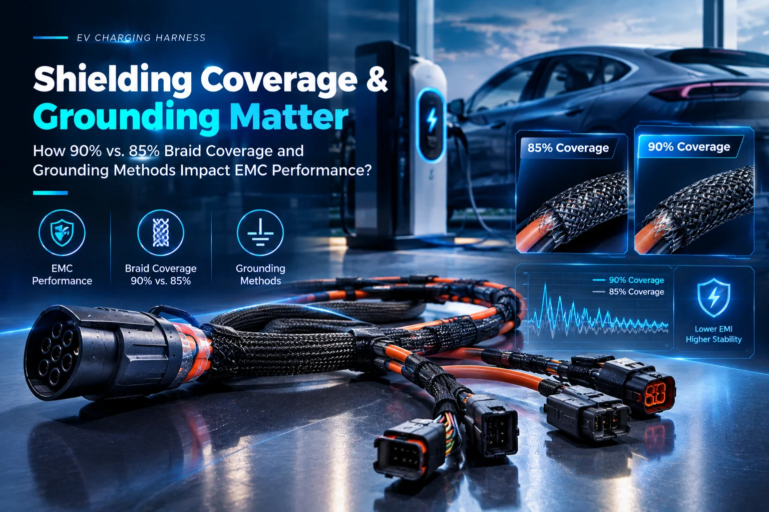
EV High-Voltage Cable Harness Shielding: Braid Coverage and 360° Termination
For electric vehicle manufacturers and automotive component buyers, EV high-voltage cable harness shielding plays a critical role in electromagnetic compatibility (EMC), electrical system reliability, and vehicle-level compliance. Poor shielding continuity can allow electromagnetic interference (EMI) to escape from high-voltage cables, potentially affecting sensitive electronic systems.
However, a braided shield that looks complete does not automatically guarantee effective electromagnetic protection. Braid coverage, material conductivity, transfer impedance, and connector termination all influence shielding performance.
For procurement teams and quality engineers, two factors deserve particular attention: braid coverage and 360-degree shield termination. Understanding how these parameters interact helps buyers evaluate high-voltage cable harness suppliers beyond visual inspection.
1. Why EV High-Voltage Cable Harness Shielding Matters
High-voltage EV systems use power electronics to control energy conversion, battery charging, and electric motor operation. Fast switching transitions in inverters, onboard chargers, and DC-DC converters can generate broadband electromagnetic noise.
High-voltage cables may carry this noise along the vehicle’s electrical architecture. Without effective shielding and proper bonding, electromagnetic fields can couple into nearby circuits or radiate beyond the harness.
Common risks include:
- EMC test failures: Inadequate shielding may contribute to excessive radiated or conducted emissions.
- Electronic interference: Electromagnetic noise can affect nearby communication, sensing, or control circuits.
- Inconsistent product quality: Variations in braid construction and termination can create differences between production batches.
- Higher validation costs: Shielding deficiencies discovered during vehicle-level testing may require connector redesign, harness rework, or additional testing.
Effective EV cable shielding therefore requires a complete design approach. Braid construction, connector interfaces, chassis bonding, and cable routing must work together.
2. 85% vs. 90% Braid Coverage: What Should Buyers Evaluate?
Braided shielding consists of interwoven conductive strands surrounding the insulated cable core. Braid coverage describes the proportion of the underlying surface covered by the shield under a defined measurement method.
Higher coverage can reduce the size of open areas in the braid. However, coverage alone cannot determine the actual shielding effectiveness of a finished EV high-voltage cable harness.
The result also depends on strand material, braid angle, wire diameter, frequency, cable construction, and termination quality.
| Evaluation Parameter | 85% Braid Coverage | 90% or Higher Braid Coverage |
|---|---|---|
| Shield construction | More exposed openings may remain | Generally fewer exposed openings |
| Electromagnetic leakage | Depends on braid geometry and test frequency | Potentially lower leakage under comparable conditions |
| Mechanical flexibility | Depends on strand size, braid angle, and cable construction | Must be validated against bending and installation requirements |
| Transfer impedance | Must be measured or supported by test data | Must be measured; higher coverage alone does not guarantee a specific value |
| EMC compliance | Requires validation against applicable requirements | Also requires validation against applicable requirements |
Does 90% Braid Coverage Always Mean Better EMC Performance?
Not necessarily. A 90% coverage specification may provide a useful design target, but it should not be treated as a universal automotive requirement.
For example, two cables with similar braid coverage can exhibit different transfer impedance because of differences in conductor materials, braid geometry, and shield continuity at the connector.
Similarly, a high-coverage braid may still perform poorly if the shield is terminated through a long, narrow drain-wire connection.
Procurement recommendation: Specify the required braid coverage in the cable drawing or technical specification, then verify it alongside electrical shielding performance and connector termination requirements.
3. Transfer Impedance: A Key Metric for Cable Shielding Performance
Transfer impedance ((Z_t)) is an important parameter for evaluating cable-shield performance. It describes the relationship between current flowing on the shield and the resulting longitudinal voltage developed inside the shielded structure, normalized by length.
It is commonly expressed in milliohms per meter (mΩ/m).
In general, lower transfer impedance indicates better shielding performance against shield-current coupling under comparable test conditions. However, transfer impedance is frequency-dependent and does not describe every aspect of electromagnetic shielding.
For EV high-voltage cable harnesses, buyers should evaluate the complete measurement conditions rather than comparing isolated figures.
Key items to verify include:
- Frequency range: Confirm that the test covers the frequencies relevant to the application.
- Test method: Review the applicable standard, fixture configuration, and measurement procedure.
- Cable construction: Ensure that the tested sample matches the specified conductor, insulation, braid, and jacket construction.
- Termination configuration: Confirm whether the test evaluates the cable alone or includes the intended connector and shield termination.
- Acceptance criteria: Establish the required performance limits based on the system design and EMC validation plan.
A target such as 10 mΩ/m at 100 MHz may be appropriate for a particular project, but it should be supported by application requirements and verified test data. It should not be presented as a universal threshold for all EV charging harnesses.
4. Pig-Tail Grounding vs. 360° Shield Termination
Even a well-designed braided shield can lose effectiveness when its connection to the connector or chassis is poorly engineered.
The shield termination is the electrical interface between the cable’s conductive shield and the surrounding conductive enclosure or connector shell. Its geometry and electrical continuity can significantly affect high-frequency performance.
4.1 Why Pig-Tail Shield Termination Can Reduce EMC Performance
A pig-tail termination gathers the shield strands into a narrow wire or short conductor before connecting them to a grounding point.
This approach may be convenient for some low-frequency applications. However, it can introduce excessive inductance in high-frequency shielding applications.
The inductive reactance of a conductor increases with frequency:
[
X_L = 2\pi fL
]
Where:
- (X_L) is inductive reactance.
- (f) is frequency.
- (L) is inductance.
As frequency increases, even a short pig-tail can introduce significant impedance. This may reduce the effectiveness of the shield connection and increase electromagnetic coupling.
The actual penalty depends on conductor length, geometry, routing, and frequency. Therefore, a fixed claim that every 10 cm of pig-tail reduces grounding effectiveness by 40% should not be used without a clearly defined and independently verified test method.
For high-voltage EV cable harnesses, procurement teams should review whether the proposed termination geometry is appropriate for the required EMC performance.
4.2 How 360° Shield Termination Improves Shield Continuity
A 360° shield termination connects the cable’s braided shield around the full circumference of the connector interface. Common implementations include EMC backshells, conductive compression rings, and appropriately designed shield clamps.
<escape> Cable braid → 360° conductive termination → Connector shell → Chassis bonding interface </escape>
Compared with a long pig-tail, a properly engineered circumferential termination can provide a shorter, more uniform current path with lower parasitic inductance.
Key advantages include:
- Improved high-frequency continuity: The shield remains connected around the connector interface.
- Reduced termination impedance: A well-designed interface can minimize impedance discontinuities.
- More consistent EMC performance: Controlled termination geometry supports repeatable manufacturing.
- Better integration: Dedicated shield clamps and backshells can simplify assembly and inspection.
However, 360° termination does not guarantee EMC compliance by itself. Contact resistance, surface preparation, corrosion protection, connector design, and chassis bonding must also be considered.
For dynamic applications, the complete assembly should be validated for vibration, bending, thermal cycling, and environmental exposure where applicable.
5. How to Verify EV High-Voltage Cable Harness Shielding Quality
Visual inspection remains useful for identifying obvious defects, but it cannot establish shielding performance on its own.
A robust incoming quality control process should combine construction inspection, documentation review, and electrical testing.
| Quality Control Item | What to Check | Recommended Evidence |
|---|---|---|
| Braid coverage | Coverage ratio, strand distribution, and visible gaps | Approved drawing and inspection records |
| Shield material | Conductor material, strand diameter, and braid construction | Material specifications and supplier records |
| Transfer impedance | Frequency-dependent shielding performance | Test report using a defined method |
| Shield termination | Circumferential contact, assembly geometry, and continuity | Connector drawings and assembly inspection |
| Electrical continuity | Connection between the shield and designated interface | Continuity or resistance test records, as applicable |
| EMC validation | Emissions and immunity performance for the intended system | Applicable laboratory or vehicle-level test reports |
| Environmental durability | Resistance to vibration, thermal cycling, and corrosion | Qualification records for the specified application |
What Should Procurement Teams Request From Suppliers?
Before approving a high-voltage cable harness supplier, request the following documentation.
1. Technical drawings and construction specifications
These should identify the braid coverage target, shielding material, cable dimensions, connector interface, and termination design.
2. Transfer impedance test reports
Reports should state the tested frequency range, measurement method, sample configuration, and acceptance criteria. Verify that the data represents the actual cable construction being purchased.
3. EMC validation records
Request evidence relevant to the intended vehicle or charging system. Depending on the application, this may include component-level tests and vehicle-level validation.
4. Material and traceability documentation
Confirm the specified shield material, production batch identification, and applicable material or process requirements.
5. Connector termination drawings
Check how the braided shield connects to the connector shell and how the shell bonds to the vehicle chassis. A drawing should make the intended shield path clear.
6. Which EMC Standards Apply to EV High-Voltage Cable Harnesses?
Automotive EMC compliance depends on the vehicle category, target market, component function, and applicable approval requirements.
Two references frequently encountered in automotive EMC discussions are:
- CISPR 25: Addresses radio disturbance characteristics and measurement methods for protecting receivers used on board vehicles.
- UN Regulation No. 10 (UNECE R10): Addresses electromagnetic compatibility requirements for relevant vehicle categories and electrical or electronic subassemblies within its scope.
ISO 15522 should not be used as a blanket reference for EV cable shielding acceptance without confirming its relevance to the specific requirement. Buyers should identify the applicable cable, component, vehicle, or system-level test method before establishing compliance criteria.
A supplier’s statement that a cable uses 90% braid coverage or 360° termination does not independently establish compliance with CISPR 25 or UNECE R10.
The final acceptance decision should be based on the applicable requirements and validated test results for the intended configuration.
7. Frequently Asked Questions About EV Cable Harness Shielding
Q1. Is visual inspection enough to verify braided shield coverage?
No. Visual inspection can identify obvious gaps, damaged strands, or inconsistent braiding, but it cannot reliably quantify coverage or confirm shielding effectiveness. Use an agreed measurement method and review relevant electrical test reports.
Q2. Is 90% braid coverage always better than 85%?
Higher coverage can reduce openings in the braided shield, but the overall result depends on the complete cable construction. Buyers should compare coverage, transfer impedance, termination design, flexibility, and verified EMC performance.
Q3. Why is 360° shield termination preferred for high-frequency applications?
A circumferential connection can provide a shorter, more uniform shield-current path than a long pig-tail. This generally helps reduce parasitic inductance and preserve shield continuity at the connector interface.
Q4. Does a 360° termination guarantee EMC compliance?
No. It is one part of the shielding architecture. Cable routing, connector design, chassis bonding, switching-noise characteristics, and the applicable test configuration also affect the final result.
Q5. What transfer impedance should an EV cable harness achieve?
There is no single value suitable for every EV high-voltage cable harness. The target depends on the application, frequency range, system architecture, and validation requirements. Establish the limit before testing and require supporting test data.
Q6. What should buyers prioritize when comparing cable harness suppliers?
Evaluate documented cable construction, shield material, braid coverage, termination engineering, traceability, test capability, and application-specific validation. A supplier that can explain and document its design decisions offers a stronger basis for technical qualification.
Conclusion: Specify, Measure, and Validate EV Cable Shielding
Reliable EV high-voltage cable harness shielding requires more than a visually complete braided layer. Braid coverage influences shield construction, transfer impedance helps quantify shielding behavior, and connector termination determines how effectively the shield continues into the surrounding conductive structure.
For procurement teams and quality engineers, the most effective approach is to define measurable acceptance criteria, review supplier documentation, inspect termination geometry, and validate the complete assembly against applicable EMC requirements.
If you are sourcing customized high-voltage cable harnesses for EV charging or automotive power systems, work with a qualified manufacturer to review shielding construction, connector interfaces, electrical requirements, and application-specific testing before production approval.